Block Diagram
Motor Subsystem for Daisy Chain Network
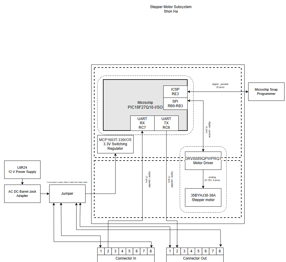
I will either take 12V from the daisy chain or from the power supply to power the daisy chain, making the power supply fully modular in case of emergencies.
Decision Making Process
My decision making process revolves around the stepper motor subsystem while following an SPI Protocol. My vision was to make my subsystem fully modular, allowing me to connect to almost any other board that follows a similar daisy chain structure while also allowing me supply or receive power from other boards. Utilizing a SPI stepper driver, it allows me to communicate to my 12V stepper motor. I use a 3.3V Switching regulator to power my PIC along with a bidirectional connection to a MPLAB Snap Programmer to program my microcontroller. As depicted in the block diagram, it includes how pins are layed out and connected to my microcontroller along with where power can be received from. The connection boxes mimic 2x4 daisy chain header pins which will allow me to communicate over UART with the rest of my team. Power can be received from either my upstream or downstream teammates as well.