Component Selection
Final Component Selection Table
| Component | Component Datasheet | Price | Picture |
|---|---|---|---|
| PIC18F27Q10-I/SO (PIC) | Link to Product | $1.45 |  |
| DRV8889QPWPRQ1 (Motor Driver) | Link to Product | $4.17 |  |
| 35BYHJ30-36A (Stepper Motor) | Link to Product | $2.65 |  |
| LM2575-3.3WU (Voltage Regulator) | Link to Product | $1.75 |  |
| L6R24-120 (Power Supply) | Link to Product | $8.95 | 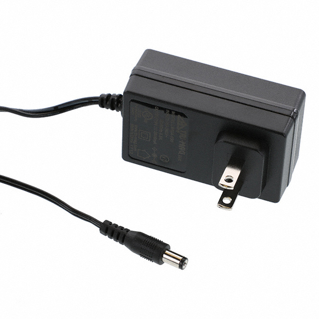 |
Final Decision Making Process
My goal for my decision-making process was to find components that were compatible with each other and had longevity. For my 3.3V Switching Regulator, I chose the SMD variant of the one used in previous labs. I was familiar with its circuitry, almost guaranteeing a working switching regulator when testing the prototype. My PIC choice was also inspired by the one used in class, as it features the same program memory and RAM size as the DIP given in class. On the other hand, both the motor driver and motor were chosen due to their affordability while also having to rely heavily on their datasheets. This allowed me to meet my product requirements, utilizing a PIC microcontroller, a 3.3V switching regulator, an SPI motor driver, and a stepper motor. I also chose a power supply with enough current to supply my needs for the entire subsystem.
Role and Responsibilities
I am responsible for the actuator and using a PIC. This will be done using a stepper motor to control the rotational movement of the solar panel so it can face the sun. I will communicate using a Serial Protocol Interface (SPI) along with a stepper motor driver. To communicate with the daisy chain, I will communicate over UART to receive data from the optical sensor, allowing the stepper motor to rotate based on where the sun is facing. The microcontroller will be powered using a 3.3V switching buck regulator and a 12V power supply to power the 12V stepper motor.
MCC Configuration
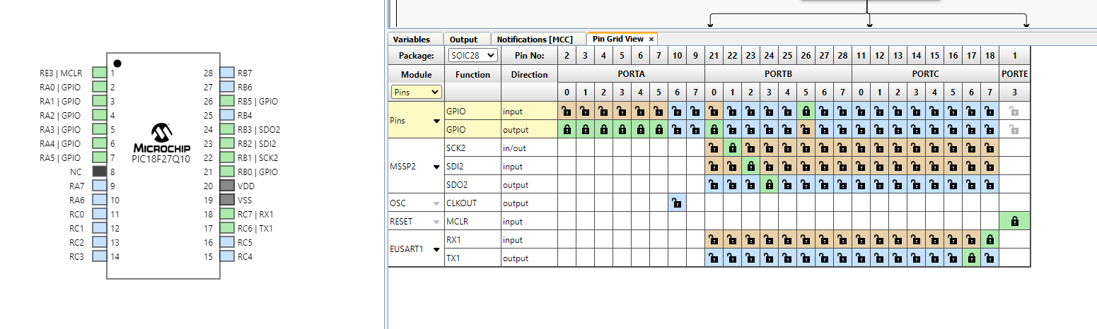
I chose a 28 pin PIC as my main microcontroller as my subsystem will initially only need about 6 pins to work effectively. Two pins are designated to RX and TX pins so I can communicate to the daisy chain network. 4 pins are designated to the stepper motor driver, focusing on SCK, SDI, SDO, and SS. We have a clock, serial input, serial output, and slave select that will connect to the stepper motor driver. Other pins are free of use and can be used for debugging purposes. RA0, RA1, and RB5 are used as debugging LEDs and push buttons. RA2-RA3 are used to power up the motor driver's nSLEEP and DRVoff pins which are needed based off the DRV8889 datasheet. RA4-RA5 were used as debugging header pins and testing. RB0 acts a digital output pin to enable and disable chip select.
PIC Rationale
| ESP Info | Answer | Help |
|---|---|---|
| Model | PIC18F27Q10-I/SO | Include the entire part number (leave off any letters at the end that specify the package type) |
| Product Page URL | Product | Do not paste links directly into the table. Use a link |
| Datasheet URL(s) | Datasheet | Do not paste links directly into the table. Use a link |
| Application Notes URL(s) | Applications | Do not paste links directly into the table. Use a link |
| Vendor link | Vendor | Digikey, Jameco, etc. Do not paste links directly into the table. Use a link |
| Code Examples | N/A | url(s) for libraries on github or other sites related to the microcontroller and your planned peripherals |
| External Resources URL(s) | External Resources | Search on Google and YouTube for other resources for each specific microcontroller. |
| Unit cost | $0.84 | Find in the Microchip online store, or Digikey |
| Absolute Maximum Current for entire IC | 350 mA | Find in the microcontroller datasheet |
| Supply Voltage Range | 2.3V-5.5V | Min / Nominal / Max / Absolute Max, as found in datasheet |
| Absolute Maximum current (for entire IC) |
250 mA | as found in datasheet |
| Maximum GPIO current (per pin) |
50 mA | as found in datasheet |
| Supports External Interrupts? | Yes | as found in datasheet |
| Required Programming Hardware, Cost, URL | MPXlabs, Snap Programmer | found on the microcontroller's product page |
| Works with MPLabX? | Yes | Required. See Microchip Development Tools |
| Works with Microchip Code Configurator? | Yes | Can be validated in MPLabX. Screenshot required. |
| Module | # Available | Needed | Associated Pins (or * for any) |
|---|---|---|---|
| GPIO | 23 | 8 | RA0-RA5, RB5, RB0 |
| ADC | 23 | 0 | * |
| UART | 4 | 2 | RC6-RC7 |
| SPI | 8 | 3 | RB1-RB3 |
| I2C | 4 | 0 | * |
| PWM | 23 | 0 | * |
| ICSP | 1 | 1 | RE3 |
| ... | ... | ... | ... |
Major Components Selection
PIC Microcontroller
-
PIC16F1503-I/SL
-
$0.99
- Link to Product
| Pros | Cons |
|---|---|
| Fast Shipping | Can't communicate over UART |
| Small for its capabilities | Has only 14 pins |
-
PIC18F27Q10-I/SO
-
$1.45
- Link to Product
| Pros | Cons |
|---|---|
| Has UART and SPI compatibility | Small programming size (28kB) compared to 128 kB used in class |
| Functions with MPX labs | Bigger compared to other options |
-
PIC18F14Q20T-I/SS
-
$1.06
- Link to Product
| Pros | Cons |
|---|---|
| UART and SPI compatibility | Compatibility issues |
| Possibly easier to solder | Has only 14 pins |
Choice: Option 2 PIC18F27Q10-I/SO
Rationale: I chose this specific microcontroller because it can communicate with UART and use an SPI to effectively control my stepper motor driver. It also has the necessary pins for the entire subsystem, leaving out extra pins for debugging purposes. It also works with MPX labs and the snap programmer. It also needs around 2.3V -5.5V to power which works perfectly with the switching regulator. The max current for GPIO pins are 50 mA and about 250 mA for the entire package. A 24kB programming memory should also get the job done.
Motor Driver
-
DRV8434SRGER
-
$3.13
- Link to Product
| Pros | Cons |
|---|---|
| Can communicate with SPI | Hard to solder/almost impossible |
| Cheaper option | Complicated IC factor |
-
DRV8434SPWPR
-
$3.21
- Link to Product
| Pros | Cons |
|---|---|
| Several half bridges | Bigger than other options |
| Cheaper option | Sensitive Configuration issues |
-
DRV8889QPWPRQ1
-
$4.17
- Link to Product
| Pros | Cons |
|---|---|
| Can communicate with SPI | Expensive option |
| Stall detection and SPI modes | Only fit for one stepper motor |
Choice: Option 3 DRV8889QPWPRQ1
Rationale: I chose option 3 because it is able to support a 12V stepper motor. It is also compatible with my PIC I chose after doing some research. Although it is the most expensive option, it also has good thermal padding and operating temperatures.
Stepper Motor
-
35BYHJ30-36A
-
$2.65
- Link to Product
| Pros | Cons |
|---|---|
| Cheapest option | 7.5 degree step angle |
| Reliable for testing | Thermal issues |
-
QSH4218-51-10-049
-
$67.78
- Link to Product
| Pros | Cons |
|---|---|
| Bipolar/hybrid | Super expensive |
| Used on 3D printers | Out of budget |
-
42M100B1B
-
$37.73
- Link to Product
| Pros | Cons |
|---|---|
| Bipolar/hybrid | No datasheet and hard to wire |
| Decent fit for project scope | expensive with no room for error |
Choice: Option 1 35BYHJ30-36A
Rationale: I chose option 1 because it is by far the cheapest out of all the options as stepper motors are really expensive. It also has bipolar capabilities, being able be controlled bidirectionally in response to project constraints.
12V Power Supply
-
SWI3-5-N-MUB
-
$4.90
- Link to Product
| Pros | Cons |
|---|---|
| Cheapest option | Low current output |
-
QSH4218-51-10-049
-
$6.75
- Link to Product
| Pros | Cons |
|---|---|
| Smallest charging block | Low current output |
- L6R24-120
- $8.95
- Link to Product
| Pros | Cons |
|---|---|
| High current potential | Most expensive option |
Choice: Option 3 L6R24-120
Rationale: I chose option 3 because it supplies the highest current which will be needed for my stepper motor. I will have extra current in case of power budgetting issues.
3.3V Switching Regulator
-
TLV61048DBVR
-
$0.63
- Link to Product
| Pros | Cons |
|---|---|
| Cheapest option | 6 pin configuration |
| Supplies high current | No thermal connections |
-
TLV61046ADBVR
-
$1.09
- Link to Product
| Pros | Cons |
|---|---|
| Adjustable regulator | 6 pin configuration |
| Reasonable price | No thermal connection |
-
LM2575-3.3WU
-
$1.75
- Link to Product
| Pros | Cons |
|---|---|
| Buck regulator | Smaller input voltage range |
| 5 pin configuration | Most expensive option |
Choice: Option 3 LM2575-3.3WU
Rationale: I decided on option 3 because it has a similar pin configuration as the 3.3V regulator we designed in class. It is also a buck regulator, having a higher efficiency than most regulators. It also can take an input of 12V which is the amount of power coming from the daisy chain network.