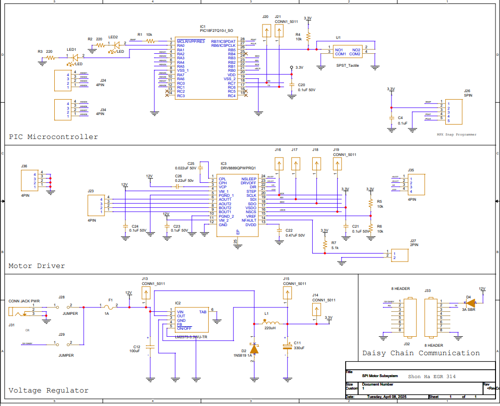
Schematic Design
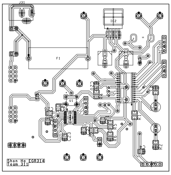
PCB Design
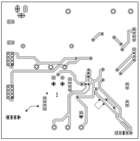
Top Layer
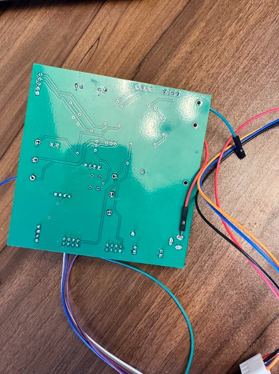
Bottom Layer
User Satisfaction
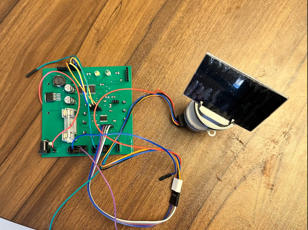
The functionality of the motor subsystem satisfies user needs because it is essentially the backbone of this project. The sensors, HMI, and MQTT all rely on the feedback control the motor receives as it controls the direction of the solar panel, being the spotlight of this project. We want to educate students K-6 on solar power and the benefits of sustainable energy practices. All other subsystems are inputs for the motor as they analyze light levels, manual button controls, and mode toggling, which all fall under the motor. The stepper motor brings the project to life. It also satisfies product requirements as it fits under a bi-directional motor requirement as the motor adjusts itself in a 360 based on real-time sensor data received or if a particular button is toggled when in manual control.
Decision Making Process
Our team's design for the motor subsystem is centered around precision, reliability, and compatibility. Stepper motors are reliable in moving heavier loads such as solar panels due to their high torque output and are more precise than your average DC motor as they use step sizes to move precisely. We selected a 12V stepper motor because of its ability to provide exact positioning and also due to its torque factor to ensure that it can spin a chassis with the solar panel attached to it. The DRV8889-Q1 was chosen for its many advantages as an SPI motor driver. It features a nFAULT output system that allows me to determine what is faulting the motor driver along with its many CTRL registers that control speed, current, stalling, and positioning.
Version 2.0
If I were capable of designing another version for my current motor subsystem, there would be many changes I would make to improve the overall design and add more functionality. It was initially intended to have two stepper motors, but the price of motor drivers was exceedingly high. One motor would offer the 360 rotation, which it currently has, but the other would add its tilt functionality to the solar panel to adjust its positioning from day to night. This would add more functionality for the solar tracker as a whole. I would also replace my motors with more expensive ones. During testing, my motor would be exceedingly hot after about five minutes of being connected to my board. This is due to how stepper motors operate, as it takes current for the motor to remain stationary. Outside of class, I would have also moved away from MPLAB and PIC microcontrollers as it proved challenging to program SPI and use the snap programmer. Another addition would be switching from SPI to PWM outside of class, as attempting to figure out SPI with the datasheet was tedious.
Some minor hardware changes include getting a more miniature fuse holder, as the one I initially chose took up a decent chunk of the board. Another significant change I learned is never to leave any pins floating, especially for IC chips, as you never know what might need to be jumped. I experienced many difficulties soldering wires to small solder pads as I realized that some pins on my motor driver were essential for full functionality. I would have also loved to add an extra debugging button as it would be easier to debug certain things, such as the manual control of my stepper motor. It would also be essential to note that I should always double-check the datasheet because sometimes my circuit wouldn’t function properly if I didn’t ground something, especially my motor driver’s thermal pad. Another important note to self, especially when designing a PCB, is to leave a safety margin for traces to the board outline, as all of my PCB boards were faulty due to a trace being too close to the board outline, causing me to jump a wire from my barrel jack to the jumper.